淬火膨胀仪
A family of quenching dilatometers used to study the heat treatment of steel and metal alloys to identify the heating rate, the quenching rate and the isothermal dwell times necessary to yield the crystalline structure to meet the required physical properties.
Sales PromotionsThe DIL805 Series comprises of four models: DIL 805L, DIL 805A are quenching dilatometers, DIL 805A/D is a quenching with the capability to deform the specimen by compression, and DIL 805A/D/T that can also stretch it in tension mode.
All four instruments are fully automated, self-contained units used to measure dimensional changes under extreme conditions of controlled heating and cooling.
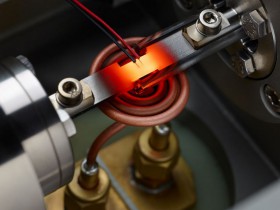
In the quenching mode the sample, solid or hollow, is inductively heated to a temperature plateau and is then cooled at an user-defined (linear or exponential) cooling rate. The phase transformation occurring in the continous cooling process or in the isothermal dwell, with or without compression/tensile stress, is indicated by the measured change in length. An array of cooling or isothermal curves represents a continous-cooling-transformation (CCT) diagram or an isothermal time-temperature-transformation (TTT) diagram, respectively. DIL 805A represents today the benchmark for determining these dimensional changes and phase transitions. Operating from -160°C up to 1500°C (in two different furnace configurations) with heating rates of up to 4000°C/s and cooling rates of 2500°C/s, can closely simulate the material response for any production or heat treatment process.
The DIL 805A/D, on top of the quenching mode, is distinguished by its capability to deform the specimen with controlled deformation rates of of 0.01 to 200 mm/s. Used to optimize steel processes like hot or cold rolling, DIL 805A/D allows to develop time-temperature-transformation diagrams after deformation (DTTT) and is also used to examine creep and relaxation processes.
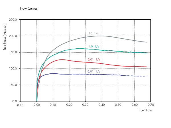
DIL 805A/D/T further extends the capabilities to alternate tensile and compressive loading to emulate mill processing. Moreover, tensile loading to fracture lends additional information about material’s final performance and allows to generate true-stress vs true-strain or stress/strain cycling plots.
|
DIL 805L |
DIL 805A |
DIL 805A/D |
DIL 805A/D/T |
|
| Temperature Range: (sample dependent) |
-150°C to 1300°C |
-150°C to 1300°C |
50°C to 1500°C |
50°C to 1500°C |
| Heating principle: | inductive | inductive | inductive | inductive |
| Sample material: | Electrically conductive hollow or solid body | Electrically conductive hollow or solid body | Electrically conductive solid body | Electrically conductive solid body |
| Sample Geometry: | OD 4mm Length 10mm |
OD 4mm Length 10mm |
OD 5mm Length 10mm |
OD 5mm Length 10mm |
| Length Resolution: | 50 nm | 50 nm | 50 nm | 50 nm |
| Temperature Resolution: | 0.05°C | 0.05°C | 0.05°C | 0.05°C |
| Atmosphere: | inert gas, vacuum, air | inert gas, vacuum, air | inert gas, vacuum, air | inert gas, vacuum, air |
| Heating rate Cooling rate: |
2000°C/sec 2500°C/sec | 4000°C/s 2500°C/sec |
100 °C/s 100°C/sec |
100 °C/s 100°C/sec |
| Deformation force: | up to 20.0 kN | up to 8.0 kN | ||
| Deformation rate: | 0.01 – 200 mm/s | 0.01 – 20 mm/s | ||
| Strain rate φ: | 0.001 – 20.0 s-1 | 0.001 – 20.0 s-1 | ||
| True strain φ: | 0.05 – 1.2 | 0.05 – 1.2 | ||
| Minimum Gauge Length: | 3 mm | 3 mm | ||
| Number of deformation steps: | any number | any number | ||
| Pause between deformation steps: | 60 msec | 60 msec |
DIL 805A Quenching Dilatometer – Measurement Principle
DIL 805A Quenching Dilatometer – Measurement Principle

The DIL 805A(*) is used to observed dimensional changes under extreme conditions of controlled heating and cooling. A solid or a hollow sample is inductively heated to a temperature plateau and is then continuously cooled with different (linear or exponential) rates. The phase transformation occurring in the continuous cooling process or in the isothermal plateau (which may also be a multi-step transition) is indicated by the measured change of length. An array of cooling curves represent a continuous or an isothermal TTT diagram (Time-Temperature- Transformation diagram). The beginning and end of the transformation indicate the alloy phase boundaries, e.g. ferrite, carbide, graphite, pearlite, bainite, martensite or other eutectoid phase batches.
(*): The “A” designation is from the German “Abschreck” for quenching
DIL 805A/D, Quenching and Deformation Dilatometer– Measurement Principle
DIL 805A/D, Quenching and Deformation Dilatometer– Measurement Principle

The DIL 805A/D extends the principle of the DIL 805A to also include controlled deformation. At a user-defined temperature a solid sample is compressed with various deformation programs (e.g. linear, multi-level stage, with constant deformation rate, with constant force). As with the quenching dilatometer it is now possible to carry out a cooling process in order to create a DTTT diagram (Time-Temperature-Transformation diagram after Deformation). The DIL 805A/D is also used to examine creep and relaxation processes.


